This article is about a transistor
mixer circuit that I made:
Step 1: Design the Circuit
I have drawn the circuit via
PSpice Simulation software student edition:
Calculate the steady state Vc value:
Vc = Vs - Beta * Ib * Rc
= Vs - Beta * (Vs - Vbe) / (Rb1 + Rb2) * Rc
= 3 V - 100 * (3 V - 0.7 V) / (140 kohm + 10 kohm) * 1,000 ohms
= 3 V - 100 * (3 V - 0.7 V) / 150,000 ohm * 1,000 ohms
= 3 V - 1.53333333 V
= 1.46666666667
Step 2: Simulations
Simulations show that my circuit has a high gain.
This might not be true for practice.
Transient:
Frequency Domain:
Step 3: Make the Circuit
Step 4: Testing
Distortion Adjustment Video:
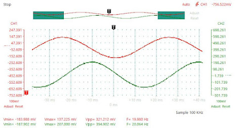
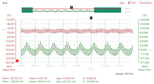
I used Instrustar USB Oscilloscope for testing.
20 Hz Input:
1 kHz Input:
20 kHz Input:
100 Hz and 1 kHz Sine Wave Inputs:
100 Hz Triangle and 1 kHz Sine Wave Inputs:
Testing showed that output signal needs to be small to
maintain the mixer output linearity because of the connected LEDs.
Conclusion
You can implement the circuit with only one LED. This LED would be LED1 in the circuit diagram.


No comments:
Post a Comment